
We have been testing a new suspension that features a component not found on the Elise or Exige. This innovation is a rear swaybar (anti-rollbar) that was developed by our partners in Italy, DNA Racing. This rear swaybar allowed us to test softer springs than we typically run. We've spent several weeks testing on the road and track. We recruited our friend and pro-Ride & Handling Engineer, David Thilenius for set-up and tuning. Our focus was to create a fantastic handling car for the street and occasional track use. We were focused on delivering a flat handling car with grip and compliance, especially on rough roads and tracks. All the work was conducted on our street legal '05 Elise.
We tested the following:
- Spring rates:
- 250lbs/350lbs
- 350lbs/500lbs
- 450lbs/600lbs
- Valving
- 2 different levels
- Swaybar settings:
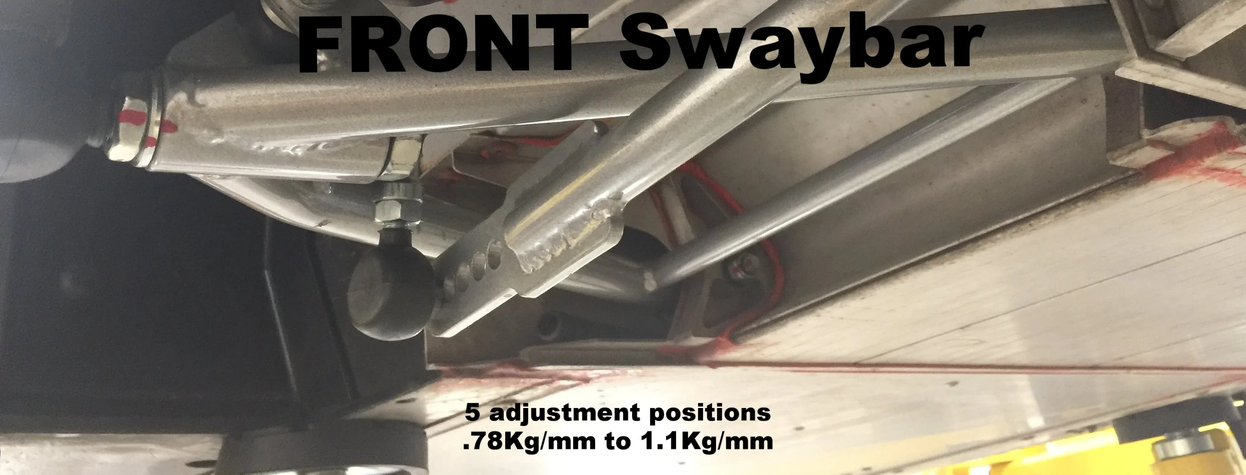
- Front: 20mm bar with 5 positions
- .78Kg/mm to 1.1Kg/mm
- Rear: 20mm bar with 4 positions
- .93Kg/mm to 1.235 Kg/mm
- Front: 20mm bar with 5 positions
The key advantage of the rear bar is that you can run softer springs than normal. Swaybars are used to help manage large side-to-side body movements (body roll). Running softer springs deliver a more compliant ride and more grip. Without a rear bar, we've had to run heavy springs in an effort to better control the car and to reduce body roll. The downside of a rear swaybar is the added complexity and cost. Check this reference for more details: Wikipedia
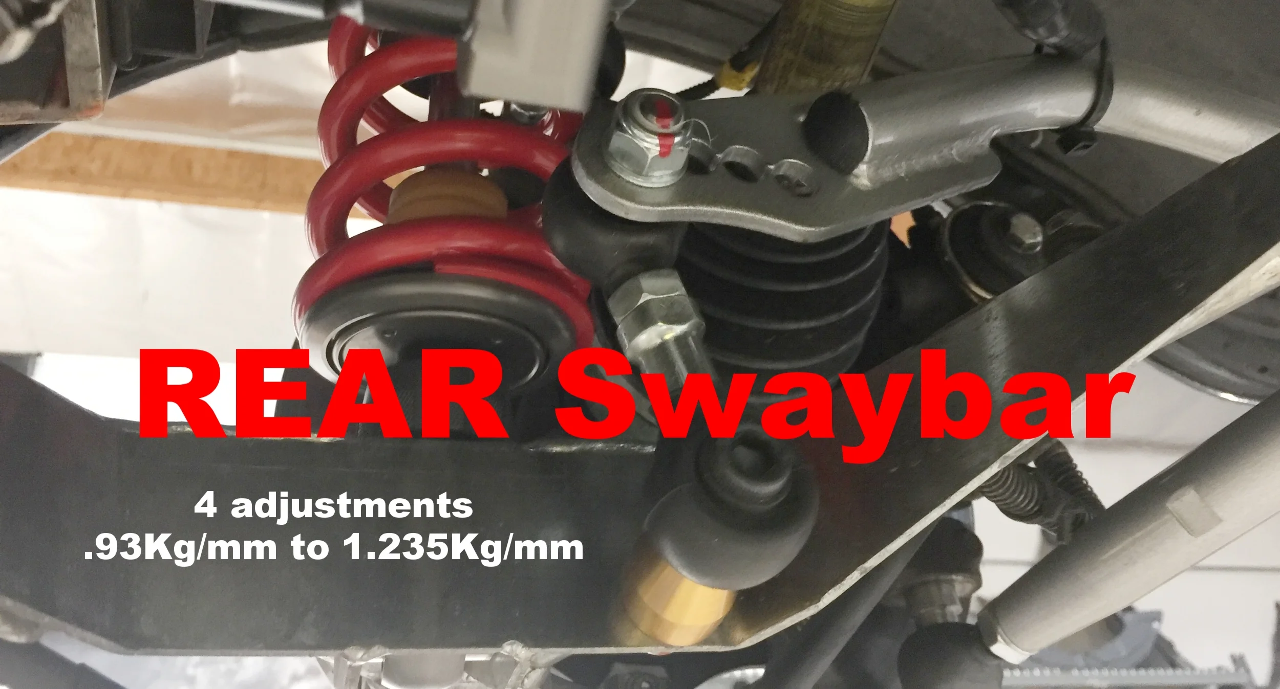
Rear swaybar with 4 adjustments. Requires drilling one hole into the lower wishbone as shown above.
We started with 450/600 spring rates but then switched over to even softer rates than we have ever run: 350lbs front & 500lbs rear. We completed most of our testing with Triple Adjustable dampers with our V2 valving developed by our good friend Ralph@V2 Motorsport. This gave us a wide latitude to test. A future blog will cover the details of the dampers and settings.
Dave T. spent a day running our Elise on his development route through SoCal roads to dial in his tuning. His final settings proved to be good but firm. He also had the dampers set at almost full soft and recommended that we revalve the dampers as well as other areas to find additional compliance. I drove the car and was impressed but wanted to take it to the West Coast Lotus Meet to really put some miles on this set-up.
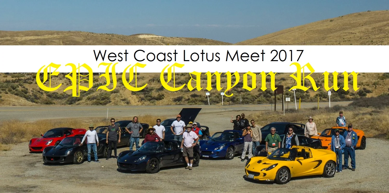
The West Coast Lotus Meet trip included a several-hour freeway trip to reach the location and one EPIC canyon run that took most of the second day. The suspension felt good and performed very well as I hung with the tour leader for hours through some great but rough canyon roads. I knew this was a nicely balanced kit BUT it was still a bit stiffer than I wanted. It was more comfortable than the factory Sport suspension but stiffer than the factory Standard suspension. I wanted the best of both worlds.
We had the dampers revalved to shift the curve to deliver more comfort but kept enough to make it stiff enough for the track. We also placed the softer 250/350 springs on to help. Dave was recruited once again to have a go. The advantage of a professional is that you can get excellent data fairly quickly. It took him another day of tuning to land on a setting that struck the best balance. I took the car out onto my favorite test canyon road and was truly impressed. The compliance and grip were what I was hoping for. The car turns in flat and sharply. The soft suspension soaked up the rough roads without beating me up.

Track testing was our next objective. I decided to drive the car to Spring Mountain and softened the Rebound 5 more clicks to see the effect. It was even better on our bump-strewn freeways. SoCal has expansion joints that are notoriously bad and can make a Sport pack Lotus feel like a bucking bronco. Our new suspension was perfectly comfortable yet still sporty and responsive. My goal is to create a useable sports car that you can take on trips and yet still strafe a canyon or run an occasional track day, not a boulevard cruiser.

Spring Mtn was running the East 1.6mile course. This is a fast and smooth course but has many curbs that you can ride that can upset a less forgiving suspension. After stiffening rebound to Dave’s road settings, I went out to do some warm-up laps and quickly realized that the car was too soft for the track. We decided to put the swaybar onto the stiffest settings to see if that would help the wallowly response on track. This proved to be a disaster as the car turned in quickly but understeered horribly. I took one lap on track and exited immediately to make a change as it was almost undrivable! It took us another few different iterations of settings on the swaybars and the dampers to get the car to my satisfaction. I like a neutral-handling car that maintains a nice balance. The final setting was exactly what I liked.
I had a couple of Lotus owners drive the car to get their feedback as well. Steve drove the car on track and was very impressed. He has owned an Elise for 10 years and has done at least 60 track days so is very dialed into this platform. He also has the Ohlins TTX dampers yet was very impressed with our kit. Watch his video testimonial: Click HERE or below.
At this point, we are ready for production parts. We placed an order with our partner and expect to see production parts by the end of Dec or early Jan'18.
One additional configuration that we need to test is running this rear swaybar with the factory non-adjustable bar. I'm not overly optimistic as the torsional stiffness of the factory bar may be too light - even after drilling a new hole to increase stiffness. We try it out this coming week... (UPDATE Edit: stock front bar works. New Blog will be posted soon)


